Ejector pin marks silently sabotage countless builds. Here’s the precise, field-tested process every U.S. modeler needs to banish those ugly divots for good—and stop them from ruining another finish.
The Tiny Blemishes That Wreck Big Builds
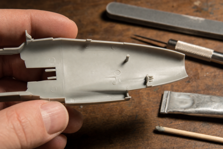 At IPMS (International Plastic Modelers Society) contests, basic construction quality — including ejector pin mark removal — is the first and primary judging criterion. Even the most meticulously painted and weathered model will lose points to a well-prepared but plainly finished competitor if surface flaws are present. That same standard applies to every model on the workbench, contest-bound or not. There is a moment almost every scale model aircraft builder has experienced: a fuselage is primed for the first time, the gray mist settles, the modeler steps back—and a row of perfectly round, shadow-casting depressions snaps into sharp focus along the inner wing surface, fully visible through an open wheel well. This is the ejector pin mark moment, and it is one of the most common and demoralizing discoveries in the hobby.
What makes it so frustrating is that it is almost always preventable—not by switching to a different kit brand, but by learning to identify and address these marks before assembly begins, not after. Every injection-molded plastic model aircraft kit produced anywhere in the world carries ejector pin marks. This includes highly regarded kits from Tamiya, Revell, Academy, and Hasegawa, as well as budget brands and older toolings. In recent years, manufacturers have gotten better at hiding ejector pin marks in inconspicuous places—but eventually, every builder will need to remove some.
Understanding the problem—what ejector pin marks are, why they exist, and exactly how to eliminate them—transforms a frustrating surprise into a manageable, predictable step in the build process. By the end of this guide, the reader will possess the exact process to fix ejector pin marks on any plastic model airplane, regardless of experience level.
What Exactly Are Ejector Pin Marks—And Why Do They Happen?
To understand ejector pin marks, it helps to understand how plastic model kits are manufactured. In the injection-molding process, liquid polystyrene thermoplastic is injected under high pressure into precision-machined steel molds. The mold consists of two halves: a core and a cavity. Once the molten plastic fills the cavity and cools sufficiently to hold its shape, the two halves separate—and at this point, a system of cylindrical metal pins called ejector pins is driven forward to push the solidified part free of the mold cavity.
Wherever an ejector pin contacts the warm plastic during ejection, it leaves a mark. The most common result is a recessed ejector pin mark: a shallow circular depression, typically 0.01 to 0.2mm deep, circular and smooth. Causes include excessive ejection force, insufficient cooling time, and improper pin placement. Less frequently, slightly raised circular witness marks form when mold tolerances allow the plastic to flow slightly around the pin base.
Not every mark demands repair. Marks on surfaces that will be fully enclosed after assembly—the underside of a cockpit tub, the ceiling of a closed wheel well, the inside faces of glued fuselage halves—require no attention whatsoever. Only marks on visible exterior surfaces and visible interior areas (cockpit walls, wheel well walls seen through open doors, bomb bay floors) must be corrected. The first question any experienced modeler asks when encountering a mark is: will this be visible on the finished model? If the answer is no, it gets a pass.
As for why manufacturers haven’t eliminated the problem: ejector pins are not optional. They are the primary mechanism by which injection-molded parts are extracted from their tooling without damage. The geometry of complex aircraft parts—compound-curved fuselage halves, detailed landing gear bay ceilings—often leaves few locations where ejector forces can act without landing on surfaces that will be visible in the finished model. As kits become more detailed, the challenge compounds.
What You’ll Need Before You Start: The Complete Workbench Checklist
Before picking up a sanding stick or opening a tube of putty, gather every item on this list. Running short of a critical supply mid-repair is one of the most common reasons beginner modelers rush a fix—and end up redoing it.
Fillers and Putties
Tamiya Basic Type Putty (No. 87053) — A lacquer-based tube putty widely recommended for medium-depth depressions. It sands easily and feathers into surrounding plastic. Apply with the tip of a hobby knife blade, a piece of plastic, or a dedicated putty tool. Thinnable with lacquer thinner for liquid application.
Squadron White Putty — An American hobby staple with decades of proven use in the modeling community. Widely available at Hobby Lobby, Micro Mark, and major online retailers. Performs similarly to Tamiya Basic Type Putty; thinnable with lacquer thinner.
Cyanoacrylate (CA/superglue) — Available in thin, medium, and thick (gel) viscosities. Thin CA wicks into fine depressions via capillary action. Medium CA is the standard choice for moderate-depth marks (approximately 0.3–0.5mm). Thick/gel CA handles deeper marks (greater than 0.5mm). CA does not shrink and can be sanded within 60 seconds of accelerator application.
CA Accelerator (Zip Kicker or similar) — Instantly cures CA upon contact. Use sparingly on visible surfaces—excess accelerant makes the cured CA harder to sand, and CA can become hot and develop a whitish, crusty appearance when over-accelerated.
Mr. Surfacer 500 (Gunze Sangyo/Mr. Hobby) — A thick liquid surfacer/filler for near-flush or very shallow marks. Applied by toothpick or fine brush directly to the defect. Dries in approximately 30 minutes. The 500-grade designation indicates particle size, similar to the concept of sanding grits; it provides more gap-filling potential than finer grades.
Milliput Superfine White (two-part epoxy putty) — For very large or structurally significant depressions where solvent-based putties are inadequate. For unusually large, wide depressions — such as an oversized pin mark on a flat wing panel — punch or cut a thin disc from spare styrene sheet, glue it flush over the recess with liquid cement, allow full cure, then sand and fill any remaining edge gap with thin CA or Mr. Surfacer 500. Water-soluble before curing; dries with approximately the same hardness as polystyrene. For standard ejector pin marks, Tamiya putty or CA glue will handle the vast majority of situations; Milliput is most relevant for filling large structural gaps.
Sanding and Finishing Tools
- Sanding sticks or abrasive papers in graduated grits: 220, 320–400, 600, 800, and 1000
- Flexible sanding sponge block for curved fuselage surfaces, cowlings, and engine nacelles
- Carbide scriber in a pin vise (or a sewing needle as an effective substitute)
- Dymo label machine tape (thick plastic type) or metal scribing template for panel line re-scribing
- Gray primer: Mr. Surfacer 1000/1200, Tamiya Fine Surface Primer, or Badger Stynylrez Primer (airbrush-ready)
- Raking light source: a desk lamp or natural window sidelight angled at 15–20 degrees to the part surface. This is the single most consistently overlooked tool among beginners.
- 3x–5x magnification loupe or OptiVisor headband magnifier
- Fine-tip pencil for marking problem spots during inspection
- Isopropyl alcohol (IPA) and cotton swabs for cleaning parts before priming
- Masking tape to protect adjacent engraved panel lines during aggressive sanding
- Toothpicks: the universal applicator for putty, CA glue, and Mr. Surfacer 500
How to Fix Ejector Pin Marks on Plastic Model Ai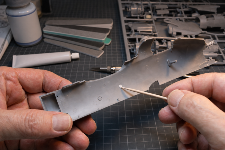
Step 1: Find Every Pin Mark Before You Glue Anything
The single most important step in the entire repair process is identifying and mapping all ejector pin marks before any glue contacts the kit. This prevents the most common and most frustrating beginner error: discovering a visible mark after the fuselage halves are permanently cemented together, when the mark is now surrounded by finished structure and accessible only at an awkward angle.
The raking light technique: Hold each part under a single directional light source angled at approximately 15 to 20 degrees to the part surface. Rotate the part slowly. Depressions cast distinct, visible shadows under raking light that completely disappear under flat overhead illumination. Natural daylight from a window at a shallow angle works equally well and costs nothing.
The mapping process:
- Remove all parts from the sprue and clean up sprue gate attachment points.
- Hold each part under raking light and rotate it through all angles.
- Mark every located depression and raised witness mark with a fine-tip pencil circle.
- Dry-fit the assembly without glue to determine which pencil-marked spots will be visible in the finished model.
- Any mark that will be fully enclosed and invisible after assembly can be erased from the repair list. All others go on it.
- Photograph or sketch the dry-fitted assembly from multiple angles to create a reference map.
Pay particular attention to cockpit tub walls, wheel well walls visible through open bay doors, and bomb bay floors. These surfaces carry ejector pin marks that are fully visible through open hatches and canopies in the finished model and must be treated exactly like exterior marks. This inspection step takes 10 to 15 minutes and saves hours of downstream rework.
Step 2: Match Your Filler to the Mark’s Depth and Location
Applying the wrong product is the single biggest source of frustration for beginners. Using heavy putty on a shallow mark creates far more sanding labor than necessary. Using thin CA on a very deep mark results in multiple applications and potential cracking. The correct filler is determined by mark depth and surface geometry. Use the decision matrix below before picking up any product:
| Mark Type | Depth | Recommended Filler |
| Raised witness mark | Raised | No filler — scrape flush with No. 11 X-Acto blade, then sand |
| Near-flush, barely detectable | Near-flush | Mr. Surfacer 500 applied by toothpick |
| Shallow recessed depression | Up to ~0.3mm | Mr. Surfacer 500 applied by toothpick; thin CA as alternate |
| Moderate recessed depression | ~0.3–0.5mm | Medium CA glue; Tamiya Basic Type Putty or Squadron White Putty as alternate |
| Deep recessed depression | >0.5mm | Thick (gel) CA, or tube putty in stages |
| Deep on curved/flexible surface | >0.5mm, compound curve | Thin CA or Milliput epoxy putty |
CA glue is now the most commonly recommended primary filler among experienced modelers for the majority of ejector pin marks. As noted in FineScale Modeler, superglue “provides a fast and smooth finish once sanded”—particularly valuable for natural metal finish (NMF) work, where it can be polished as smooth as the surrounding plastic, unlike porous tube putty, which can telegraph under NMF.
Step 3: Fill Smart—Slightly Proud, Never Flush
The critical technique that separates successful repairs from repairs that have to be redone: deliberately over-fill every mark. Apply filler so it sits fractionally above the surrounding surface plane, never flush with it.
All solvent-based fillers—Tamiya putty, Squadron White, Mr. Surfacer 500—shrink as solvents evaporate during curing. A fill that looks perfectly level when applied will have pulled down below the surface level once fully cured, leaving a residual bowl that telegraphs under primer. Applying a slightly proud fill and sanding back to the surface plane after curing reliably compensates for this effect.
For tube putties (Tamiya Basic Type, Squadron White):
- Squeeze a small amount of putty onto a piece of paper or glass surface.
- Use a flat-ended No. 18 X-Acto blade or a toothpick to apply precisely to the ejector pin mark.
- Use the minimum amount needed. Too much increases sanding work and risks marring adjacent detail.
- Apply so the putty domes slightly above the surrounding surface.
- For thick putty fills, apply in two or three thin stages, each fully cured before the next. Thick single applications shrink dramatically.
- Apply masking tape flanking the repair area before puttying to limit cleanup.
- Allow a full 24 hours before sanding. Sanding wet putty pulls material out of the depression, creating a crater worse than the original mark.
For CA glue:
- Place a small drop of CA on a glass or ceramic surface.
- Use a toothpick or fine wire to wick or dab it precisely into the depression.
- Swirl the CA around the depression perimeter to ensure full edge contact.
- Apply a small amount of accelerator (Zip Kicker). CA is fully cured and sandable within 60 seconds.
- Note: medium CA left to cure naturally (without accelerator) produces a slightly softer cure that is somewhat easier to sand.
For Mr. Surfacer 500:
- Apply directly from the bottle cap using a toothpick or old dedicated brush.
- Apply a slightly generous amount over the mark.
- Allow to dry until the surface transitions from wet/shiny to matte—approximately 20 to 30 minutes at room temperature.
- If still deficient after sanding, reapply without sanding in between.
Step 4: Sand Through the Grits—Patience Is the Whole Game
Once the filler is fully cured, sand back to surface level using a graduated abrasive sequence. This is the most time-consuming and most technique-sensitive step in the entire process.
| Grit | Use | Notes |
| 220 | Heavy putty removal only | Use sparingly — removes surface detail quickly |
| 320–400 | Shaping and leveling fills | Standard working range |
| 600 | Scratch removal; texture restoration begins | |
| 800 | Fine finishing | Use wet for best results |
| 1000 | Final pre-primer finish | Wet sand; essential before gloss/metallic finishes |
| 1200–2000+ | Polishing primer before NMF | Micro Mesh cloths; mirror finish for metallic paints |
Critical sanding techniques:
- Hold sanding tools flat and apply even pressure. Rocking the sanding stick creates low spots that telegraph under paint.
- On curved surfaces—fuselage halves, cowlings, wing leading edges—use a flexible sanding sponge block, not a rigid flat sander. Rigid flat sanding creates obvious flat spots on compound curves that become glaring faults under gloss and metallic finishes.
- Wipe the surface with a damp cloth between grits to remove dust and accurately evaluate remaining scratches before committing to the next grit.
- Protect adjacent recessed panel lines with masking tape during aggressive sanding. Apply tape along both sides of any panel line that runs near the repair area before any sanding begins.
- Wet sanding—using water on the sanding stick or abrasive paper—consistently produces a smoother finish on putty, reduces dust, and keeps the abrasive surface clear of clogging. Use it from 800 grit upward.
Step 5: Prime the Repair—The Truth Coat That Reveals Everything
Once sanding is complete and the surface looks smooth on bare polystyrene, the repair is not finished. A thin coat of gray primer is the only reliable diagnostic tool for evaluating a sanded repair. The unaided eye cannot reliably detect micro-scratches, witness halos, or residual surface texture on bare polystyrene—primer makes every flaw instantly visible under raking light.
Application:
- Clean the model surface with IPA applied via a soft toothbrush or cotton swab to remove all sanding dust and skin oils. Contamination prevents primer adhesion.
- Apply a thin, misting coat of gray primer over the repair area and a surrounding zone of approximately 10 to 15mm.
- Allow full drying per the primer product’s instructions.
- Inspect under raking light, rotating the part slowly.
Four failure indicators to look for under primer:
- Residual depression bowl — the fill shrank; the surface is still below the surrounding plane. Return to Step 3.
- Raised perimeter halo — filler edges were not sanded completely flush. Return to 400-grit sanding focused on the perimeter edge, then re-prime.
- Color contrast ring — a tonal difference between filler and polystyrene telegraphs through primer. Apply additional thin primer coats or lightly sand the primed area and re-prime.
- Visible sanding scratches — grit progression was not carried far enough. Return to 800-grit wet, then 1000-grit wet, before re-priming.
Expect to prime, detect, sand, and re-prime at least once per repair. As one modeling reference describes this stage, it is the “last chance to repair problems before the finish coats.” This iterative loop is not a sign of failure—it is the process working exactly as intended.
Re-scribing panel lines: If sanding has abraded adjacent recessed panel lines, re-scribe them before the final paint coat—never after. Once the primed surface is confirmed flat, align Dymo tape or a metal scribing template along the intended line using surviving sections as alignment references. Draw the scriber lightly in three to four initial passes to establish the line, then deepen gradually over successive passes. Apply a drop of Tamiya Extra Thin cement into the finished channel; capillary action will draw it along the scribed line and clean the channel. Brush out debris with a stiff brush to finish.
The repair is complete when a thin coat of gray primer shows a completely uninterrupted, featureless surface under raking light from all angles.
The Most Common Ejector Pin Mark Mistakes—and How to Avoid Every One
Mistake 1: Sanding Before the Putty Is Fully Cured
Solvent-based putties remain soft for the first several hours after application. Sanding wet putty does not level it—the abrasive pulls and rolls the soft material out of the depression, making the mark worse than before and leaving an uneven surface that dries with striations and pores. Allow a minimum of 24 hours under normal room conditions before sanding any tube putty.
Mistake 2: Over-Filling with Too Much Putty in One Application
Thick tube putty applications shrink dramatically as solvents evaporate. The correct approach for deeper marks is two or three thin application stages, each fully cured before the next. This incremental approach is slower but produces far superior results with less total sanding work.
Mistake 3: Skipping the Primer Check
The most experienced modelers use primer as a diagnostic tool after every repair cycle, not just before the final paint coat. Painting directly over a sanded repair without priming is gambling that the repair is invisible—a gamble that regularly fails, especially under gloss and metallic finishes.
Mistake 4: Ignoring Interior Pin Marks That Are Partly Visible
Cockpit tub walls, wheel well walls, and bomb bay floors carry ejector pin marks that are immediately visible through open hatches and canopies in the finished model. They require the same preparation and repair attention as exterior surfaces.
Mistake 5: Over-Sanding and Removing Recessed Panel Lines
Apply masking tape along both sides of any panel line running near a repair area before any sanding begins. This is the simplest, most effective prevention for a problem that creates a cascade of additional repair work.
Bonus Technique: Mr. Surfacer 500 as a Floating Agent
After a spot-filled area has been sanded to apparent flatness, brush a very thin coat of Mr. Surfacer 500 over the entire repair zone with an old dedicated brush. This floats the repair into the surrounding plastic surface, blending the filler-to-plastic transition zone invisibly before the primer coat.
When Things Go Wrong: Your Ejector Pin Mark Repair Troubleshooting Guide
Problem: The Putty Keeps Cracking After It Dries
The depression is too deep for single-stage tube putty, or the plastic section beneath the mark has slight flex. Tube putty requires a rigid, stable substrate; if the plastic flexes during cure or sanding, the putty cracks and detaches. Switch to thin or medium CA for this specific mark. Clean out the cracked putty, degrease with IPA, wick thin CA into the depression, accelerate, and proceed to sanding.
Problem: The Repair Shows a Distinct Halo or Ring in the Primer
The filler was not sanded completely flush at its perimeter edges—a very slight raised rim remains where filler meets surrounding plastic. Return to 400-grit sanding focused specifically on the halo location, feathering the transition from filler edge to plastic. Wipe, inspect under raking light, then re-prime.
Problem: CA Glue Flooded Adjacent Panel Lines and Sealed Them
Do not attempt to re-cut CA-sealed panel lines with an X-Acto blade—this typically damages the surrounding plastic. Once the primed surface is confirmed flat, re-scribe the sealed lines using Dymo tape or a metal scribing template as a guide, with a carbide scriber and light progressive passes along the original line path, using surviving sections of the line as alignment references.
Problem: The Repair Looks Perfect on Bare Plastic but Reappears as a Shadow Under Gloss or Metallic Paint
Micro-scratches from insufficient sanding grit progression are invisible on bare polystyrene but fully visible under gloss and metallic finishes. Metallic finishes amplify even the tiniest surface imperfection. Wet-sand the repair zone to 1000 grit and re-prime before re-applying paint. For natural metal finishes, the primed surface should be polished after application—sometimes using Micro Mesh cloths down to 4000 grit—to achieve the mirror-smooth surface metallic paints require.
Problem: A Re-Scribed Panel Line Looks Wavy or Inconsistent
The scribing guide slipped during cutting, or too much pressure was applied on initial passes causing the tool tip to wander. Fill the errant scribe mark with a drop of thin CA, allow full cure, sand flush, and re-scribe with a fresh guide alignment. Practice on an inconspicuous surface—the underside of a wing panel or a spare piece of polystyrene—before scribing on visible areas.
Frequently Asked Questions About Fixing Ejector Pin Marks on Model Airplanes
Q1: How do I step by step fix a deep ejector pin mark on a plastic model airplane without buying expensive putty?
CA (cyanoacrylate) superglue is the most accessible, fast-curing filler for deep ejector pin marks and is available at every hardware and hobby store in the USA. Medium-viscosity CA works best for marks in the moderate-depth range of approximately 0.3–0.5mm; switch to thick (gel) CA for marks deeper than 0.5mm.
- Inspect the mark under raking light to confirm depth and extent.
- Clean the area with isopropyl alcohol on a cotton swab; allow to dry fully.
- Place a small drop of thick (gel) CA on a glass or ceramic surface.
- Use a toothpick to wick or dab the CA into the depression, deliberately slightly over-filling.
- Apply a small amount of accelerator (Zip Kicker or similar); the CA will be rock-hard within 60 seconds.
- Sand flush using 400-, 600-, and 800-grit abrasives in sequence.
- Apply a thin coat of gray primer and inspect under raking light. If all four failure indicators are absent, proceed to paint.
No proprietary modeling putty is required. The CA method produces a repair that polishes as smooth as the surrounding plastic—ideal for metallic finishes.
Q2: What is the best filler putty for fixing ejector pin marks on Tamiya and Revell model airplane kits?
The top-rated fillers for ejector pin marks on Tamiya and Revell polystyrene kits are Tamiya Basic Type Putty (No. 87053) for medium-depth depressions, CA glue for deep and fast-cure needs, and Mr. Surfacer 500 for near-surface shallow marks.
- Tamiya Basic Type Putty: Lacquer-based; sands easily and feathers nicely into the surrounding plastic. Apply with a toothpick, allow 24 hours to cure, then sand progressively through the grits.
- Squadron White Putty: American hobby staple widely available at Hobby Lobby and Micro Mark. Thinnable with lacquer thinner for liquid application. Performs similarly to Tamiya Basic Type Putty.
- Surfacer 500: Best for near-flush marks; applied by toothpick, allowed to dry approximately 30 minutes, then sanded. Also serves to blend the repair zone seamlessly into the surrounding plastic surface.
All three products are suitable for beginner use when used with adequate ventilation.
Q3: How do I find all the ejector pin marks on my model airplane kit before I start building?
The raking light technique is the definitive method for locating every ejector pin mark on kit parts before assembly.
- Remove parts from the sprue and clean up gate attachment points.
- Hold each part under a single directional light source angled at approximately 15 to 20 degrees to the part surface.
- Rotate the part slowly through 360 degrees.
- Depressions cast distinct shadows under raking light that are invisible under flat overhead illumination.
- Mark every located depression with a fine-tip pencil circle.
- Dry-fit the assembly to determine which marks will be visible in the finished model. Any fully enclosed mark can be ignored.
Natural daylight from a window at a shallow angle is equally effective as an artificial lamp. This step takes 10 to 15 minutes and saves hours of downstream rework.
Q4: What is the exact process for re-scribing panel lines that I accidentally sanded off while fixing ejector pin marks?
Re-scribing panel lines is a straightforward process once the repair is primed and confirmed completely flat. Do not attempt to re-scribe on bare, unprimed plastic.
- Confirm the primed repair surface is flat and featureless under raking light before starting.
- Align a Dymo label machine tape (thick plastic type) or metal scribing template along the intended line, using surviving adjacent line sections as alignment references.
- Press the guide firmly against the surface.
- Draw the scriber lightly along the guide edge in 3 to 4 initial passes to establish the line location only, not depth.
- Increase pressure gradually over successive passes, deepening the channel incrementally.
- Check under raking light after every 3 to 4 passes.
- Apply a drop of Tamiya Extra Thin cement into the finished channel; capillary action cleans and smooths the scribed line.
- Clean the channel with a stiff brush to remove plastic debris.
If the scribing tool slips and creates an errant scratch, fill it with a drop of thin CA, allow full cure, sand flush, and re-scribe with a fresh guide alignment.
Q5: How do I tell if an ejector pin mark repair is truly finished and ready for paint on my model airplane?
The repair is finished only when a thin coat of gray primer applied over the repair area shows a completely uninterrupted, featureless surface under raking light—no exceptions.
Four failure indicators that require a return to the sanding stage:
- Residual depression bowl: filler shrank; re-fill and re-sand.
- Raised perimeter halo: filler edges not sanded flush; target the halo with 400-grit, then re-prime.
- Color contrast ring: tonal difference between filler and polystyrene; apply additional thin primer coats or lightly sand and re-prime.
- Visible sanding scratches: grit progression insufficient; wet-sand to 800 then 1000 grit before re-priming.
If all four failure indicators are absent and the primed surface shows no interruption or shadow from any angle, the model is ready for paint.
Key Takeaways
- Every injection-molded plastic model airplane kit contains ejector pin marks—from Tamiya, Revell, Academy, Hasegawa, and every other manufacturer—and identifying them under raking light before assembly is the single most important step in the repair process.
- Match your filler to the mark’s depth: CA glue for deep depressions (fast cure, no shrinkage, ideal for NMF); Mr. Surfacer 500 for near-flush shallow marks; medium CA glue or tube putty (Tamiya Basic Type or Squadron White) for moderate-depth depressions, applied in thin, fully cured stages.
- Always fill slightly proud of the surface—all solvent-based fillers shrink as solvents evaporate, and a flush application will cure below the surface plane.
- Gray primer is the only reliable diagnostic tool for evaluating a completed repair—the unaided eye cannot detect micro-scratches and witness halos on bare polystyrene.
- Re-scribe any erased panel lines before the final paint coat, never after—and never attempt to re-cut CA-sealed lines with an X-Acto blade; use a carbide scriber with a guide.