



Stop Snapping Parts Off by Hand — Here’s the Proven Two-Cut Process for Clean Sprue Removal on Plastic Model Airplane Kits
The Moment Every Builder Recognizes
Open a new plastic model airplane kit, and the temptation hits fast. The parts are right there on their plastic framework, the connection points look thin enough to snap cleanly, and the build is waiting. So you grip a part and twist — and a second later, you’re looking at a white stress mark, a missing chunk of wing, or a cracked antenna mount that needs repair before the build has even started.
Every modeler who works with plastic model airplane kits has been in that moment. The impulse makes sense: those plastic tabs connecting parts to their framework do look thin enough to break cleanly. The reality is different. The polystyrene in injection-molded kits is specifically engineered to resist tearing, and under hand pressure, it almost always stress-marks or cracks rather than shearing clean at the gate — frequently pulling material off the part itself.
Proper sprue removal on plastic model airplane kits takes minutes to learn and delivers measurably better results from the first part. It rests on three foundations — the right tools, a disciplined planning step, and a precise two-cut technique. This guide covers all three in the sequence a builder actually uses them.
Understanding the Sprue: What You’re Actually Working With
The plastic framework inside every model kit box is the product of injection molding. Molten polystyrene is injected under high pressure through a precision metal mold, travels through a network of channels, fills every part cavity, and solidifies within seconds. When the mold opens, the result is a single, interconnected piece of plastic — parts and framework fused together as one object. That framework is what U.S. modelers call the sprue or the tree. The more precise industrial term for the channels is runner.
Parts and their framework were not assembled — they were molded together. There is no joint to exploit, no designed break point in the system, except for one deliberate exception: the gate.
The gate is the narrow tab connecting each individual part to the runner — intentionally the thinnest, weakest point in the system, engineered to be the separation point when parts are removed after molding. That thinness makes the gate cuttable, but also vulnerable: when a cutting tool compresses rather than shears the plastic, the stress travels into the part surface and produces white stress marks — hair-line micro-cracks in the polystyrene structure itself, not surface contamination.
After the first cut separates a part from the runner, the small remnant of gate material on the part is the nub or stub. Removing it cleanly is Step 2 of the process.
KEY TERMS AT A GLANCE
| Sprue | The complete plastic framework holding all kit parts, produced by injection molding. |
| Runner | The technical term for the channels in the sprue that distributed molten plastic to the part cavities during molding. |
| Gate | The small, thin tab connecting each individual part to the runner; intentionally the thinnest and weakest point. |
| Nub / Stub | The small piece of gate material remaining on the part after the first cut; removed with a second pass and sanding. |
| Flash | Thin, unwanted excess plastic along part edges from mold misalignment or imperfection; more common in older or limited-run kits. |
The Right Tools for the Job
The most common source of damaged parts during sprue removal is not technique — it is the wrong tool. Fingers, scissors, and household pliers apply uncontrolled force across the gate, almost guaranteeing stress marks, cracks, or missing material. Three tools cover every scenario on a plastic model airplane kit.
Sprue Cutters (Parts Nippers)
The primary cutting tool is the flush-cutting parts nipper — also called a sprue cutter or side cutter. These specialized cutting pliers have precision-ground jaws designed to shear polystyrene rather than crush it. Xuron is one of the most established names in the category, frequently cited by experienced modelers as a reliable, proven tool. Tamiya also makes a well-regarded model, and budget alternatives are available at most hobby retailers.
The operating detail beginners most consistently miss: the flat side of the nippers must always face the part, not the sprue runner. When the flat jaw presses against the part, compression goes into the waste material on the sprue side. Reverse that orientation and compression goes directly into the part surface — producing stress marks even from a perfectly sharp tool. Quality nippers are a worthwhile investment; dull edges require more force, which increases stress transferred to the part regardless of orientation.
The Hobby Knife
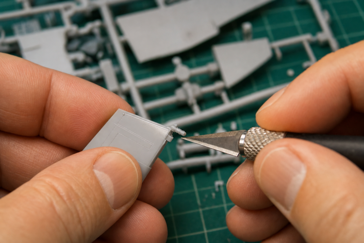
The essential secondary tool is the X-Acto No. 1 handle fitted with a No. 11 blade — the established U.S. scale modeling standard. The No. 11 blade’s narrow, pointed profile is precisely suited to the shaving, slicing, and scraping motions used during stub removal and flash cleanup.
The single most critical maintenance habit: replace the blade regularly. A fresh No. 11 blade slices polystyrene cleanly with light pressure. A dull blade drags, requires significantly more force, and either tears the plastic or skips unpredictably — increasing both part damage and the risk of cutting your fingers. Keep a supply of fresh blades at the workbench, change at the first sign of resistance, and always cut on a self-healing cutting mat away from your fingers.
Sanding Sticks and Files
After cutting comes finishing. A coarse-to-medium sanding stick levels gate nubs without rounding adjacent surface detail. Jewelers’ files — also called needle files or Swiss files — reach gate points that a flat sanding stick cannot access: curved surfaces, recessed attachment points, and edges of slots and holes.
Before You Cut: The Planning Step Most Beginners Skip
Read the instruction sheet completely before touching a single sprue. It is not supplementary documentation — it is the first step of every build. It establishes the assembly sequence and provides the part number key that corresponds to numbers molded directly into the sprue beside each part.
Skipping this step has predictable consequences. Builders who remove all parts from all sprues at the start end up with an unorganized pile of unlabeled plastic, small identical-looking parts that cannot be distinguished, and a build sequence that immediately breaks down. The correct discipline: only remove a part from the sprue when it is needed for the current assembly step.
For parts that need to come off early — for pre-painting or because they sit awkwardly in the framework — use a fine-point black Sharpie to write the part number directly on the face of the part while it is still on the sprue. That number transfers with the part and survives handling.
During planning, identify which parts are easier to paint before removal. Landing gear legs, propeller blades, wheel hubs, drop tanks, and small accessories are more practical to paint while still on the runner, which acts as a natural handle. Leave these on the sprue through priming and painting; the gate area will need a touch-up coat after removal. If any parts broke free during shipping, secure them immediately on labeled masking tape.
The Step-by-Step Sprue Removal Process
Step 1 — Make the First Cut Away From the Part
The foundational rule: never cut flush to the part surface on the first pass. Using parts nippers with the flat jaw facing the part — or a hobby knife for gated areas nippers cannot reach — cut the runner at a point that intentionally leaves a stub of approximately 1 to 2 mm attached to the part.
When nippers close on polystyrene, the jaws compress the material before severing it, generating a stress zone on both sides of the cut. Placing the cut at a safe distance keeps that stress zone in the stub — waste material — rather than in the part surface. The stub is removed in Step 2; any stress it carries goes with it.
For parts with multiple attachment points, complete all first cuts before moving to stub removal; trimming stubs while other connections remain intact applies uneven stress and can crack the part.
Step 2 — Remove the Stub With a Second Cut
Two techniques, depending on stub size and geometry:
Hobby knife shave: Hold the No. 11 blade nearly parallel to the part surface and shave the stub away in multiple light passes rather than one aggressive cut. If the blade drags, replace it.
Despruing tweezer cutter: For smaller stubs on accessible areas, this stainless-steel, tweezer-form snipping tool — available from Micro-Mark and specialty model suppliers — trims the nub with far less leverage than full-size nippers, making it ideal for stubs that are already small or in tight locations.
In both cases: bring the stub as close to flush as possible without scoring the part surface.
Step 3 — Refine and Smooth With a Sanding Stick
After stub removal, a small rough patch typically remains. Sand in one consistent direction with a coarse-to-medium sanding stick, then follow with finer grit. Check by looking along the surface at a low angle and by touch. For curved or recessed gate points, use a round or half-round jewelers’ file rather than a flat sanding stick.
Step 4 — Check for Flash and Mold Seam Lines
Inspect the entire part for flash and mold seam lines. Trim flash — thin films of excess plastic along edges — with the hobby knife. Remove seam lines using adzing: hold the No. 11 blade perpendicular to the surface and scrape back and forth along the seam; follow with a fine sanding stick.
Important: do not confuse seam lines with molded-in surface detail like panel lines and rivet rows. Seam lines follow the mold’s parting path; molded-in detail follows the aircraft’s design and must be preserved.
Step 5 — Organize Each Part Immediately
Place each completed part in a labeled plastic bin organizer or on a strip of masking tape with its part number written in pencil. Never set a cleaned part loose on the workbench. Once a part leaves the sprue, its molded number is gone. Unlabeled parts in a pile cost significantly more time to identify later.
Special Situations: Handling Tricky Parts
Delicate and Fragile Parts
Antenna mounts, cockpit details, landing gear door actuators, pitot tubes, and similar fine features need a different approach. Standard full-size nippers can crack or distort these parts even with correct jaw orientation. The despruing tweezer cutter is the recommended tool here — its form limits mechanical leverage to the point where it cannot over-squeeze a thin feature. For the most delicate work, the hobby knife alone, used with light pressure well away from the part, may be preferable to any nipper-type tool. Cut farther from the part than normal, and take more passes on the stub.
Thick Gate Points on Large Parts
Large fuselage halves and wing sections are sometimes attached to their runners through considerably thicker gate points. Forcing full-size nippers on these risks cracking the part or dulling the blades. The solution: use the hobby knife with multiple incremental passes, or — for the heaviest attachments — a jeweler’s saw (also called a razor saw), whose fine-toothed blade removes material by cutting rather than compression. The governing rule: if the tool requires significant force, switch tools.
Parts That Are Best Painted on the Sprue
Once the planning phase has identified which parts benefit from pre-painting, leave them on their runners through priming and painting. The runner acts as a built-in handle, keeping the part elevated and fingers away from fresh paint. After paint has fully cured, run the standard five-step removal process, then touch up the gate area with the appropriate color.
Common Mistakes and How to Avoid Them
- Breaking or twisting parts free with fingers. Polystyrene does not shear cleanly at the gate under hand pressure. The result is unpredictable and often permanent, particularly on thin, projecting features. The hobby knife and nippers are the only tools that should contact a gate.
- Cutting flush to the part on the first pass. A single flush cut places the compression zone directly in the part surface and produces stress marks in the vast majority of cases. The stub from the first cut is a deliberate safety margin — not a problem to be avoided.
- Removing all parts from all sprues before beginning. This creates a pile of unlabeled plastic and dramatically increases the risk of lost or misidentified parts. Parts come off the sprue only when needed for the current assembly step.
- Continuing with a dull blade. A worn No. 11 blade drags, requires excessive force, and is the most common cause of stress marks during stub removal. Blades are consumable items — change at the first sign of resistance.
- Forcing nippers on thick gate points. When the tool requires significant effort, the result is a cracked part. Switch to a hobby knife with multiple passes or a razor saw.
Troubleshooting: When Things Go Wrong
White Stress Marks
White stress marks are micro-cracks from compressive force during cutting — most typically from a single flush cut, excessive force, or nippers facing the wrong direction. For minor marks, pressing lightly with a fingernail can reduce discoloration by redistributing compressed material. For moderate marks, liquid plastic cement applied to the area, allowed to cure, then lightly sanded re-fuses the plastic. For significant marks, sand through progressively finer grits, apply primer, then fill any remaining defect with thin CA glue or model putty before repriming.
Accidentally Cut Into the Part
For shallow scores, liquid plastic cement fills and blends after curing — sand lightly once dry. For deeper gouges, thin cyanoacrylate in multiple coats builds up the area; sand smooth through progressively finer grits. For larger defects, model putty — Tamiya Basic Putty and Squadron Green are established U.S. products — provides a workable fill. Always prime after any fill-and-sand repair to verify the surface before painting.
Lost or Broken Small Parts
Parts that broke free before being labeled should go on masking tape immediately, then be identified by cross-referencing against the instruction sheet and remaining sprues. For cleanly broken features, cyanoacrylate re-bonds the pieces with a strong joint. Parts lost entirely may require sourcing a replacement sprue from the kit manufacturer — many sell individual sprues — or finding a donor from a duplicate kit.

Key Takeaways
- Use the two-cut method every time. First, cut approximately 1–2 mm from the part surface to leave a stub. Remove the stub with a sharp No. 11 blade in multiple light passes. Never attempt a single flush cut.
- Flat jaw to the part — always. The flat cutting face of the nippers must face the part, not the runner. This single orientation detail determines whether compression goes into waste material or into the part.
- Read the instructions before cutting anything. Only remove parts from the sprue when they are needed for each sequential assembly step.
Mark parts before cutting. Write the part number on the part face with a fine-point Sharpie while it is still on the sprue. Once the part leaves the runner, the molded number is gone. - Replace dull blades immediately. A fresh No. 11 blade is one of the highest-leverage variables in clean stub removal. Change at the first sign of resistance.
- Most sprue removal damage is repairable. Plastic cement handles minor stress marks; CA glue addresses shallow scores and clean breaks; model putty fills deeper defects. Always prime after any repair to verify the surface before painting.