Crooked landing gear is the #1 finish-line heartbreak in scale modeling. Here’s the exact alignment workflow experienced builders use every single time — no special tools required.
Picture this: you’ve just put 20-plus hours into a 1/48 Tamiya P-51D Mustang. The paint is clean, the decals are down, the panel lines are crisp — everything you hoped it would be. Then you glue on the main gear struts. One tilts very slightly outward. The other pitches a hair forward. You set the finished model on your shelf and feel it immediately: the aircraft looks lopsided. That sinking feeling is one every scale modeler knows, and it almost always comes from the same place.
Landing gear misalignment is one of the most common, most preventable, and most visually damaging errors in scale aircraft assembly. Because the gear is the model’s contact point with reality — the one place where a flat horizontal surface exposes any geometric error without mercy — even small angular deviations become instantly visible. Learning how to align landing gear on a scale model airplane kit correctly is, therefore, a foundational skill that separates frustrating builds from display-quality results.
The good news: you don’t need any specialized equipment to get it right. The complete alignment process covered in this guide — dry-fitting, surface preparation, geometry analysis, jig construction, adhesive strategy, and final verification — requires only items most beginners already own. Work through it once, and you’ll never glue a crooked strut again.
Why Crooked Gear Ruins an Otherwise Perfect Build
The human eye gravitates immediately to the landing gear on a finished aircraft model, and the reason is simple: the gear is the model’s only literal contact with the ground. Any deviation from true vertical — when viewed head-on — or from the correct rake angle when viewed from the side registers as “wrong” to the viewer, even to non-modelers who can’t articulate why the model looks off. Practical modeling experience confirms that a deviation as small as 2–3 degrees from the intended strut angle is enough to make an otherwise perfect build look lopsided.
Experienced modelers sum it up directly: misaligned gear “will make all your other carefully aligned assemblies look cockeyed, too.” That’s because the gear establishes the aircraft’s relationship to the horizontal reference surface. Every other element — wings, fuselage, tail — is judged relative to how the model sits.
Most beginners encounter two main gear configurations. Tricycle gear — a nose gear plus two main gear legs — is found on most WWII jets (such as the Lockheed P-80 Shooting Star and the Messerschmitt Me 262) and virtually all modern military jets. Conventional gear, also called taildragger configuration, pairs two main gear legs with a tail wheel and is typical of most WWII prop fighters: the North American P-51 Mustang, Republic P-47 Thunderbolt, Supermarine Spitfire, Vought F4U Corsair, and Grumman F6F Hellcat. Each configuration has a distinct alignment priority, addressed step by step below.
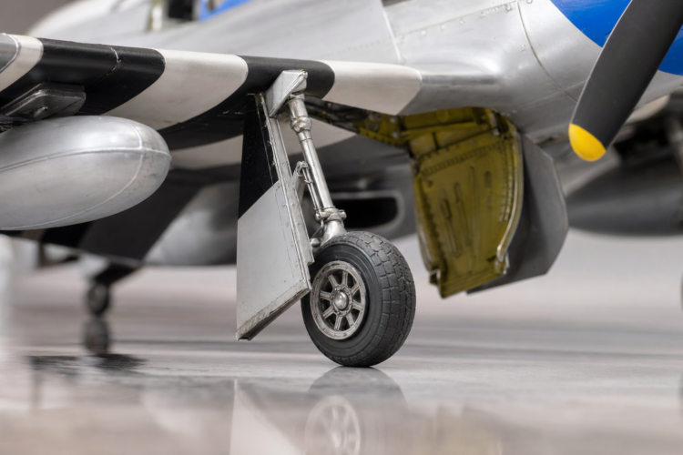
Even perfectly aligned struts can be visually undermined by gear bay doors set at the wrong angle. On most WWII aircraft, the main gear doors hang in a partially open position when the gear is deployed. A door that angles away from the fuselage at a visibly wrong attitude draws the eye away from the struts and compounds the alignment problem. That’s why door installation is the final step in the process.
On the full-scale Republic P-47 Thunderbolt, Republic chief engineer Alexander Kartveli had to build the main gear with a “shrink” mechanism that shortened it by nine inches upon retraction — enough to fold the gear into the wing while still accommodating the four outboard .50-caliber machine guns per wing — eight total. The result is a pronounced outward stance when extended: wide-track main gear that gives the Thunderbolt remarkable ground stability. A P-47 kit with struts set too vertical or too close together will immediately look wrong to any viewer familiar with the full-scale aircraft. The North American P-51 Mustang, the quintessential beginner subject, has a narrower main gear track that created what aviation historians have noted as “inherent directional instability during takeoff and landing” on the real aircraft — a subtler outward cant than the P-47, but one that must still be precise and symmetrical on the model.
What You’ll Need: The Short Shopping List
Everything on this list is widely available at hobby shops and online retailers. No specialized items are required.
- Slow-setting liquid plastic cement (e.g., Tamiya Extra Thin Cement or equivalent): The preferred adhesive for plastic-to-plastic gear joints. It melts and fuses the two styrene surfaces together, creating a bond that is actually stronger than the plastic itself. Critically, it provides a working window of approximately 20–60 seconds during which you can reposition the part before the bond becomes fixed. Apply it by capillary action: place the parts in position first, then touch the brush to the joint seam. The cement wicks in automatically.
- CA (cyanoacrylate) glue / super glue: Reserved for metal aftermarket struts or resin detail parts bonded to plastic. CA bonds in approximately 1–5 seconds, leaving no adjustment window. It is the wrong choice for primary plastic-to-plastic strut bonds because it can also cause “crazing” — a frosted, milky discoloration — on adjacent painted styrene surfaces if it contacts them.
- A flat, level reference surface: A ceramic tile, a pane of glass, or a granite surface plate. This is your most important alignment tool. To test any surface for flat, lay a known-flat straightedge across it and look for gaps.
- A small engineer’s square or right-angle reference: Used to check strut verticality from the front and sides. A small steel square is ideal; a 90-degree angle printed on card stock and cut out works perfectly for beginners.
- Masking tape or Blue-Tack / Blu-Tack: For temporary positioning during dry-fitting. Masking tape can hold a strut in approximately the correct position so you can assess the geometry before committing to glue.
- Toothpicks or micro-applicators: For precise, minimal glue placement. Applying cement with a toothpick tip gives far more control than a brush on small, delicate joints.
- Fine-grit sandpaper (400–600 grit): For cleaning glue socket surfaces before final bonding. Paint buildup and mold flash in the gear socket are leading causes of misalignment.
- Folded cardstock wedge shims: Small wedges of folded card stock or thin styrene strip used as temporary props to hold the strut at the correct angle while the cement cures.
- A reference photograph: The kit instruction sheet is the minimum — it shows intended gear geometry from front and side views. Period photographs of the actual aircraft, available from IPMS reference libraries, the National Archives, and the Air Force Historical Research Agency, provide additional confirmation of correct angles.
How to Align Landing Gear on a Scale Model Airplane Kit: Step by Step
This eight-step process applies to any injection-styrene kit in scales from 1/72 to 1/24. Work through each step in sequence — the order matters.
Step 1 — Dry-Fit Everything First, Glue Nothing
Before opening the glue, test-assemble the entire landing gear system — struts, wheels, and gear doors — and check the geometry against the kit instructions and a reference photograph. A warped wheel well insert or an out-of-square socket is dramatically easier to correct before gluing than after. Confirm that the strut locating pin or tab fits cleanly and snugly into its socket, that the strut base makes flush contact with the socket seat all the way around, and that both struts, when dry-fitted, produce an aircraft that sits without rocking on your flat reference surface. If your kit requires nose weight — as tricycle-gear kits and many taildragger kits do to prevent tail-sitting — add it now so the dry-fit reflects the actual weight distribution.
Step 2 — Clean and Prep the Mating Surfaces
Use 400-grit sandpaper or a fresh hobby knife blade to lightly abrade the glue socket on the gear bay and the locating pin or tab on the strut. Remove any mold seam lines, flash, or — critically — paint buildup from these surfaces. Paint in a gear socket acts as an unintentional shim: it raises the strut off the true socket seat and changes the geometry. This is one of the most common causes of misalignment, and one of the easiest to prevent by masking gear attachment points before painting, or by scraping paint away before final bonding. After cleaning, do a final dry-fit to confirm the strut now seats flush and produces the correct geometry.
Step 3 — Understand Your Kit’s Intended Geometry
Study the kit instructions and box art to identify three angular parameters for each main strut. Camber angle describes how far the strut leans inward or outward from true vertical when viewed from directly ahead of the aircraft — most WWII prop fighters have a noticeable outward camber, and the P-47 Thunderbolt’s wide-track gear has more pronounced outward camber than the narrower-track P-51 Mustang. Rake angle describes whether the strut tilts slightly forward or rearward when viewed from the side — most WWII prop fighters have a slight forward rake, positioning the wheels ahead of the strut attachment point. Toe angle describes whether the wheels point perfectly straight ahead or carry a slight toe-in — this is typically minimal on scale models and is primarily visible from directly below. Understanding these three parameters before gluing turns a subjective “does this look right?” check into an objective geometric target.
Step 4 — Build a Simple Alignment Jig
This is the most powerful technique in the experienced modeler’s toolkit, and it costs nothing. Tape a flat reference card — graph paper with a printed grid works perfectly — to your build surface. Use the grid lines to visually confirm that both main gear legs make identical angles relative to the fuselage centerline before the cement sets.
For tricycle gear kits, always set both main gear struts first and allow them to cure fully — overnight is recommended — before setting the nose gear. Use the cured main gear as a reference plane to determine the correct nose gear position. For conventional taildragger kits, set both main gear struts, allow to cure, then set the tail wheel using the main gear as the height reference. Setting the primary gear before the secondary gear ensures the aircraft’s primary contact points establish the correct baseline geometry first.
Step 5 — Apply Adhesive Strategically
Glue one joint at a time — never attempt both struts simultaneously. Apply a small drop of liquid cement inside the socket rather than on the strut, which pushes any excess cement into the socket interior rather than onto the visible outside surface. Press the strut into the socket and immediately check the geometry from the front. Then check from the side. Make any fine adjustments within the working window — approximately 20–60 seconds for Tamiya Extra Thin Cement. Insert small folded pieces of cardstock as temporary wedge shims between the strut base and the socket edge to hold the strut at the exact correct angle during curing. Hold or prop the part in position until the bond is firm enough to release your shims — typically 2–5 minutes — then leave the joint undisturbed overnight for full molecular fusion before stressing it.
Step 6 — Check from All Four Angles Before the Bond Fully Cures
The most common beginner mistake is checking alignment from only one angle. A strut that looks perfectly vertical from the front may lean slightly forward when viewed from the side — and that combination creates the “something is wrong but I can’t tell what” effect that frustrates finishers.
Develop this four-angle check as an automatic habit. From the front: is the strut vertical? Does it match the camber angle shown in the kit instructions? From the rear: confirm the front-angle reading from the opposite direction. From the left side: is the rake angle correct? From the right side: confirm the side reading. After each check, crouch down to display height — the height at which the finished model will actually be viewed — and sight along the gear. This eye-level check reveals angular errors that are invisible from above.
Step 7 — Install Wheels and Gear Doors Last
Wheels and gear doors go on after the struts have fully cured overnight. Installing them last means the cured struts act as a dimensional reference for setting door angles, and wheels and doors are less geometrically critical than strut angles — getting the struts right first creates a stable, correct baseline for everything that follows.
For the wheels: scrape any paint from the strut axles before gluing, apply cement inside the wheel axle hole, and set the wheel in place. Check that the wheel is not toed in or toed out when viewed from directly below. For a touch of added realism, lightly flatten the tires at the contact patch. Carefully place each assembled wheel on a slightly warm surface — an iron covered with waxed paper, or a warming tray set to low, works well for a few seconds until the plastic softens slightly, producing a gentle flat. Keep this extremely subtle — a tire that is over-flattened looks like a blown-out flat, which destroys the realism you’re working toward.
Step 8 — Final Verification on the Reference Surface
Place the completed model on your flat reference surface. It should sit without rocking. A rocking model means one or more struts is set at a different height or angle than its counterpart — the “rock test” is the definitive pass/fail check for landing gear geometry.
Additionally, measure the height of each wingtip above the reference surface with a ruler. Equal wingtip heights confirm that neither main strut is twisted in the forward-rake dimension. Any difference greater than 1–2mm in 1/48 scale is visible to the naked eye and should be addressed before the build is considered complete.
The Five Mistakes That Guarantee Crooked Gear — And How to Dodge Them
Mistake 1: Gluing to a Painted Surface
Paint buildup in gear sockets and on strut locating pins creates an imprecise fit, a weaker bond, and — most critically — altered geometry. Paint acts as an unintentional shim, rotating the strut away from its correct seated position. Prevent this by masking gear attachment points with small plugs of tissue paper or rolled masking tape before painting the underside of the model. If painting has already occurred, scrape or sand all paint from mating surfaces before bonding.
Mistake 2: Rushing or Skipping the Dry-Fit Stage
Beginners eager to reach the finish line often skip or shorten the dry-fit. This is the single most reliable way to produce misaligned gear, because problems with socket geometry, part fit, and angular parameters only become visible during dry-fitting — not after gluing. Complete a full dry-fit assembly of the entire gear system — struts, wheels, and doors — before opening the glue bottle. Photograph the dry-fit from all four angles and compare to the reference image.
Mistake 3: Checking from One Viewing Angle Only
A strut checked from only the front angle can look geometrically correct while simultaneously leaning significantly forward or backward when viewed from the side. The four-angle check described in Step 6 is mandatory, not optional.
Mistake 4: Using Fast-Setting CA Glue for Plastic-to-Plastic Gear Bonds
CA glue provides a bond window of 1–5 seconds — far too short for the careful placement, visual checking, and re-adjustment required for correct strut alignment. CA can also craze (frost and whiten) adjacent painted surfaces if it contacts them, ruining a finished paint job. Use slow-set plastic cement such as Tamiya Extra Thin Cement for all plastic-to-plastic gear joints. Reserve CA glue for metal aftermarket struts or resin detail parts.
Mistake 5: Not Accounting for Strut Deflection Under Weight
On larger scale kits — 1/32 or 1/24 — with heavy resin or metal aftermarket gear sets, the weight of the completed model can gradually deflect soft injection-molded plastic struts over months or years, causing an initially correct alignment to drift. On these larger builds, reinforce plastic struts by drilling a pilot hole through the strut’s centerline with a pin vise and inserting a length of brass or steel rod. Drill from the bottom of the strut toward the top using a bit 0.5mm smaller than the rod diameter for a tight fit, then bond the rod with a small drop of CA glue. The rod is entirely concealed within the strut and transfers the structural load through the metal core, preventing long-term deflection.
Help! My Gear Is Already Glued Crooked — Here’s Your Plan B
This happens to even experienced modelers. The goal is salvage, not perfection, and several reliable options exist depending on how severe the misalignment is and how recently the joint was bonded.
Option 1 — Heat and Re-Set (for Plastic Cement Bonds Within 24 Hours)
For joints bonded with liquid plastic cement that are less than 24 hours old, the bond can often be softened with gentle heat. Apply a hair dryer on low heat, held 3–4 inches from the joint, for 5–10 seconds. The cement bond will soften slightly, allowing the strut to be nudged into the correct position. Hold firmly in the corrected position until the plastic re-cools and the bond re-sets — approximately 30–60 seconds. Older bonds become progressively more resistant to heat correction, so act quickly.
Option 2 — Score, Snap, and Re-Bond
For severe misalignment of more than 3–4 degrees off target, the cleanest solution is to break the joint deliberately, correct the surfaces, and re-bond using the full alignment process. Use a sharp hobby knife to score the strut base around its perimeter until the part can be carefully snapped off. Sand both mating surfaces smooth with 400-grit sandpaper, remove any paint, and re-bond following the step-by-step process above. This technique requires touching up or repainting the affected area.
Option 3 — Styrene Strip Shim Correction
For minor angular deviations under approximately 2 degrees, a thin wedge shim of styrene strip placed on one side of the strut base can correct the geometry without breaking the joint. Cut a very thin strip of sheet styrene, taper one end to create a wedge, and insert it between one side of the strut base and the socket edge. Apply a small drop of plastic cement to bond the shim in place, check the geometry from all four angles, and allow to cure. Sand the shim flush, blend the area, and touch up the paint.
Option 4 — Accept and Compensate in the Base or Diorama
For minor misalignment on an already fully finished model where disassembly would cause unacceptable damage, mounting the aircraft on a display base with textured groundwork — tarmac matting, grass mat, or crushed gravel — can visually minimize the gear error by shifting the viewer’s attention to the overall scene rather than the struts in isolation. This approach is especially effective when the misalignment is small, under 2 degrees, and only visible from certain viewing angles.
One more reason to take alignment seriously: the International Plastic Modelers’ Society (IPMS) USA includes landing gear alignment as a specific criterion in competition judging. Judges evaluate strut symmetry from both the front and the side, wheel toe angle, gear door angles, and whether the model sits flat without rocking — confirming that the professional modeling community treats gear alignment not as a finishing detail, but as a primary quality indicator.
Frequently Asked Questions About Landing Gear Alignment
“How do I step-by-step align the landing gear on a plastic model airplane kit so both struts are at the same angle?”
Both main struts must be set using a flat reference surface, a right-angle check from at least four viewing angles, and slow-set plastic cement that gives you time to adjust before the bond sets.
- Dry-fit both struts without glue and check them against your kit instructions’ front-view diagram
- Clean all mating surfaces with 400-grit sandpaper to remove paint and flash
- Tape a printed grid card to your build surface as a visual reference
- Glue one strut at a time with slow-set liquid cement such as Tamiya Extra Thin
- Check from the front, rear, left side, and right side before the cement firms
- Use small folded cardstock wedge shims to hold the strut at the correct angle while curing
- Place the completed model on a flat surface — it must sit without rocking
“What is the best glue to use for attaching landing gear struts on a scale model aircraft so they don’t snap off later?”
For plastic-to-plastic gear joints, slow-setting liquid plastic cement such as Tamiya Extra Thin Cement produces the strongest and most repositionable bond; CA glue is reserved for metal or resin parts.
| Joint Type | Best Adhesive | Why |
| Plastic strut to plastic socket | Slow-set liquid plastic cement | Melts and fuses the plastic; provides adjustment window |
| Metal aftermarket strut to plastic bay | CA (cyanoacrylate) glue | Bonds dissimilar materials; use a metal pin for extra security |
| Resin detail part to plastic | CA glue with accelerator | Fast, strong bond on non-styrene surfaces |
| Large 1/32–1/24 scale plastic strut | Plastic cement + brass rod pin reinforcement | Distributes weight load through the metal core, preventing deflection |
To reinforce any strut against snapping: drill a pilot hole through the strut’s centerline with a pin vise, insert a length of steel or brass wire, and bond with CA glue before installing the strut in the gear bay.
“How do I fix landing gear that I already glued at the wrong angle on my scale model kit?”
Three repair options exist depending on how severe the misalignment is and how recently the joint was bonded.
- Heat reset (for recent plastic cement bonds under 24 hours old): Apply a hair dryer on low heat for 5–10 seconds to soften the cement bond, nudge the strut into the correct position, and hold until re-cooled
- Score, snap, and re-bond (for severe misalignment): Score around the strut base with a hobby knife, snap the joint carefully, sand both surfaces clean, and re-bond with the full alignment process
- Styrene shim (for minor deviations under 2 degrees): Insert a thin tapered wedge of styrene strip on one side of the strut base to correct the angle; sand flush and repaint after curing
If the model is fully finished and the misalignment is minor, mounting it on a textured diorama base can visually minimize the error by shifting viewer attention to the overall scene.
“Why does my model airplane lean to one side even though the landing gear looks straight to me?”
When both struts appear straight but the model still leans, the problem is usually not the gear itself — it is twist or asymmetry in the fuselage or wing assembly, which makes correctly set struts appear crooked.
- Check for wing twist: Measure the height of each wingtip above a flat reference surface. If one wingtip is higher, the wing assembly has a twist that tilts the model even when the struts are set identically
- Check for fuselage twist: Sight down the fuselage centerline from nose to tail. Any S-curve or lean in the fuselage will be transmitted to the gear
- Check for unequal strut height: Even with identical angles, if one strut is fractionally shorter due to a shallower socket or more sanding, the model will lean
The most reliable diagnostic is the wingtip-height measurement: place the model on a flat reference surface, hold a ruler vertically next to each wingtip, and compare. A difference greater than 1–2mm in 1/48 scale indicates a structural issue above the gear level.
“What angle should landing gear be on a 1/48 scale model of a WWII fighter, and how do I know if mine is correct?”
The correct gear angles for any specific WWII fighter kit are shown in that kit’s instruction sheet and should be cross-referenced with period photographs; the general rule is that most WWII prop fighters have a slight outward camber and slight forward rake on the main gear legs.
- How to read kit instructions: The instruction sheet provides a head-on view and a side view of the completed model. The angles shown in those diagrams are your target geometry
- General WWII prop fighter geometry: Main gear legs typically lean slightly outward (outward camber) when viewed head-on, giving the aircraft wide-stance ground stability. The P-47 Thunderbolt has notably wide-track gear due to its unique “shrink” retraction mechanism; the P-51 Mustang has a narrower, more vertical main gear stance
- How to verify: Place the assembled (but unglued) model on a flat surface and compare it to a period photograph of the full-scale aircraft taken from a similar viewing angle. Reference photographs from IPMS, the National Archives, or dedicated reference books show the exact geometry in real-world conditions
- The ultimate check: The completed model must sit flat without rocking, with both wingtips at equal height above the reference surface

Key Takeaways
- Dry-fitting before gluing is non-negotiable — it prevents the vast majority of alignment failures by exposing socket geometry issues, part-fit problems, and angular errors before any adhesive is applied.
- A flat reference surface and the four-angle check are your two most powerful tools — the model must sit flat without rocking, and strut angles must be verified from the front, rear, and both sides.
- Use slow-set liquid plastic cement for plastic-to-plastic gear joints — it provides the 20–60 second adjustment window that fast-setting CA glue cannot offer.
- Misaligned gear that is already cured can be corrected — heat reset, score-snap-rebond, styrene shim, and diorama-base compensation techniques each address a different severity of misalignment — full details in the Plan B section above.
- The finished gear must pass the “rock test” — the model sits flat on a level surface without rocking, and both wingtips measure at equal height above that surface.